8.7 Connecting the AC/DC output ports
8.7.1 AC OUT (AC output)
Sets the frequency weighting applied to the AC signal output from the AC/DC port located at the bottom of the device.
1Touch [Menu] on the measurement screen.
![Touch [Menu] on the measurement screen.](../images/08/07_img_1.png)
The [Menu] screen appears.
2Touch [I/O] on the [Menu] screen.
![Touch [I/O] on the [Menu] screen.](../images/08/07_img_2.png)
The [I/O] screen appears.
3Touch [Signal Output] on the [I/O] screen.
![Touch [Signal Output] on the [I/O] screen.](../images/08/07_img_3.png)
The [Signal Output] screen appears.
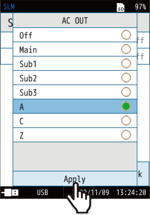
4Touch [AC OUT].
![Touch [AC OUT].](../images/08/07_img_4.png)
The [AC OUT] screen appears.
5Select the frequency weighting of the output AC signal.
| Item | Description |
|---|---|
| Off | No AC signal is output. |
| Main | Outputs an AC signal corresponding to the sound pressure waveform after frequency weighting. Applies the frequency weighting set in the selected channel. |
| Sub1 | |
| Sub2 | |
| Sub3 | |
| A | Outputs an AC signal corresponding to the sound pressure waveform after frequency weighting. Applies the selected frequency weighting. |
| C | |
| Z |
6Touch [Apply].
Important
- The continuous operating time on batteries will be shortened by approximately 30% when this function is used compared to when the setting is off.
- If both [AC OUT] and [DC OUT] are turned on, make sure that the AC/DC Output Splitter Cable CC-43S (optional) of a cable that supports simultaneous output of AC/DC OUT is connected. Connecting with the wrong adapter may damage the main unit.
AC output specifications
| Output voltage | 1 Vrms at the output level range Example: 1 Vrms at 120 dB input when the output level range setting is 120 dB |
|---|---|
| Output resistance | 50 Ω |
| Load impedance | 10 kΩ or more |
| Connection cable | BNC-pin output cable CC-24/CC-24S (BNC-miniplug) AC/DC Output Splitter Cable CC-43S * Operation with other cables is not guaranteed. |
Ideal indicated values and AC output voltage
The relationship between the indicated values (sound level Lp) of the device and the AC output voltage is shown in the figure below.
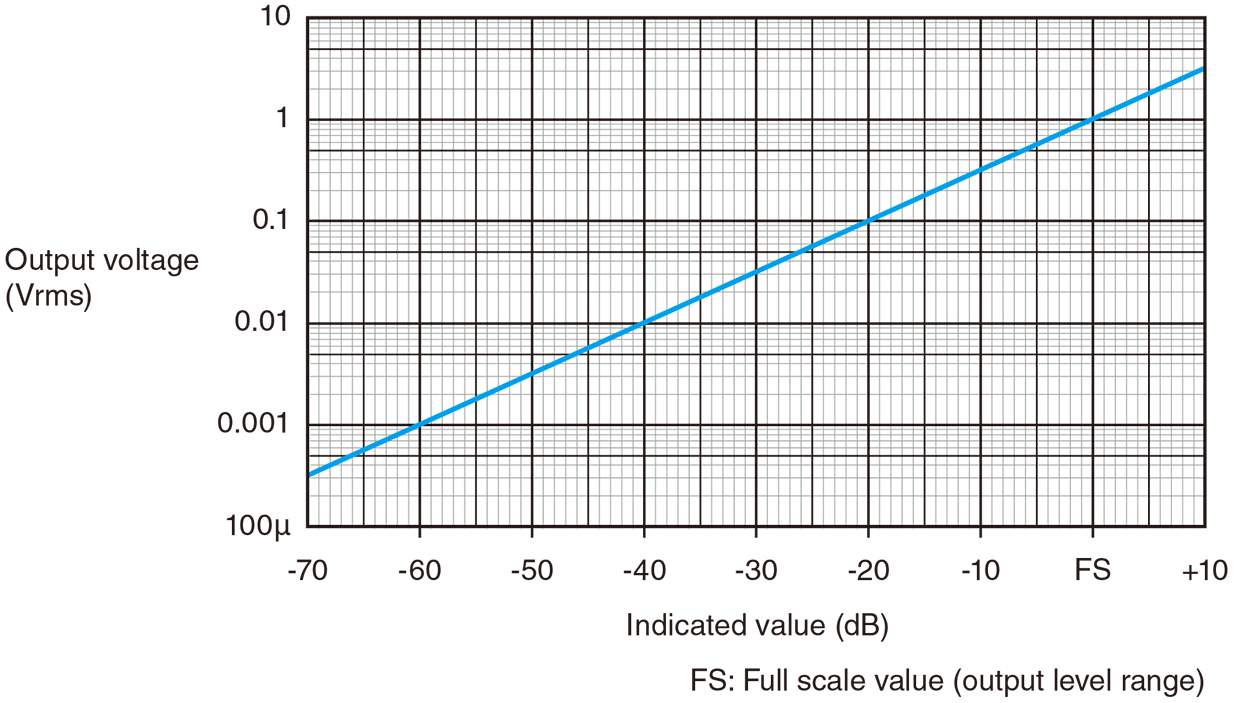
- For example, when the output level range is set to 120 dB, the output signal will be 0.5 Vrms at an indicated value of 114 dB (output level range − 6 dB).
- The actual range of output linearity is from the output level range to -60 dB.
However, if the output linearity range (60 dB) falls below the lower limit of the measurement level specification range of the Sound Level Meter, the linearity of 60 dB cannot always be maintained.
Time delay
This device converts the analog input signal from the microphone to a digital signal, performs digital signal processing with the digital signal processor (DSP), converts it back to an analog signal, and outputs the AC output signal.
Depending on the frequency, a time delay of approximately 1.3 ms occurs in the case of AC output in relation to the input signal from the microphone (Frequency weighting: Z, at 1 kHz sine wave output). However, the time delay varies with frequency.
8.7.2 DC OUT (DC output)
Set the channel for the frequency weighting and time weighting applied to the DC signal output from the AC/DC port on the bottom of the device.
1Touch [Menu] on the measurement screen.
![Touch [Menu] on the measurement screen.](../images/08/07_img_7.png)
The [Menu] screen appears.
2Touch [I/O] on the [Menu] screen.
![Touch [I/O] on the [Menu] screen.](../images/08/07_img_8.png)
The [I/O] screen appears.
3Touch [Signal Output] on the [I/O] screen.
![Touch [Signal Output] on the [I/O] screen.](../images/08/07_img_9.png)
The [Signal Output] screen appears.
4Touch [DC OUT].
![Touch [DC OUT].](../images/08/07_img_10.png)
The [DC OUT] screen appears.
5Select the channel that outputs the DC signal, and touch [Apply].
![Select the channel that outputs the DC signal, and touch [Apply].](../images/08/07_img_11.png)
| Item | Description |
|---|---|
| Off | No DC signal is output. |
| Main | Outputs a DC signal corresponding to the sound level (Lp) after frequency weighting. Applies the frequency weighting set in the selected channel. |
| Sub1 | |
| Sub2 | |
| Sub3 |
Important
- The continuous operating time on batteries will be shortened by approximately 30% when this function is used compared to when the setting is off.
- If both [AC OUT] and [DC OUT] are turned on, make sure that the AC/DC Output Splitter Cable CC-43S (optional) of a cable that supports simultaneous output of AC/DC OUT is connected. Connecting with the wrong adapter may damage the main unit.
DC output specifications
| Output voltage | 2.5 V, 25 mV/dB at the output level range Example: Outputs 2.5 V at 120 dB input when the output level range is set to 120 dB |
|---|---|
| Output resistance | 50 Ω |
| Load impedance | 10 kΩ or more |
| Applicable cable | BNC-pin output cable CC-24 (BNC-miniplug) AC/DC Output Splitter Cable CC-43S * Operation with other cables is not guaranteed. |
Ideal indicated values and DC output voltage
The relationship between the indicated values (sound level Lp) of the device and the DC output voltage is shown in the figure below.
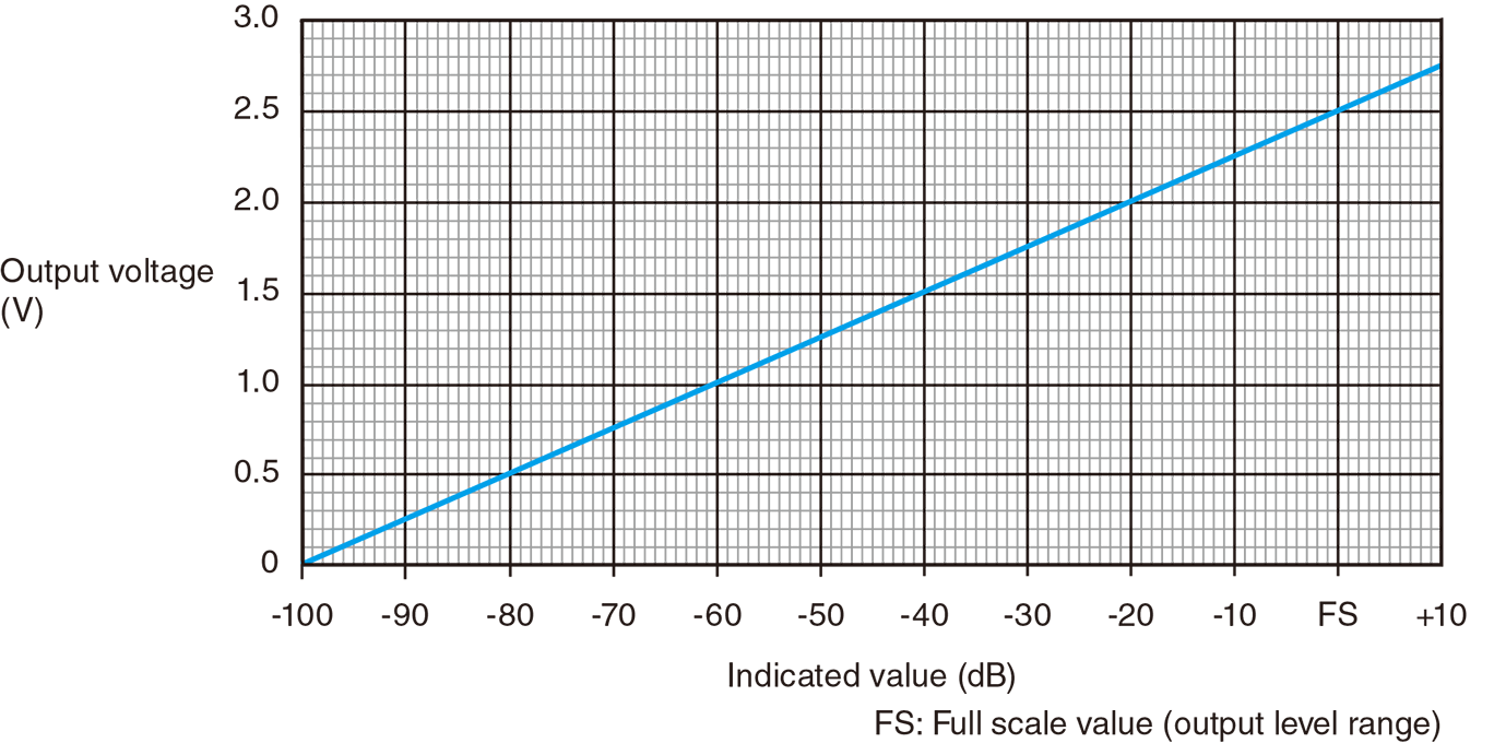
- For example, when the output level range is set to 120 dB, the output signal will be 2.35 V at an indicated value of 114 dB (output level range − 6 dB).
- The actual range of output linearity is from the output level range to -60 dB.
However, if the output linearity range (60 dB) falls below the lower limit of the measurement level specification range of the Sound Level Meter, the linearity of 60 dB cannot always be maintained.