3 Name and Function of Each Part
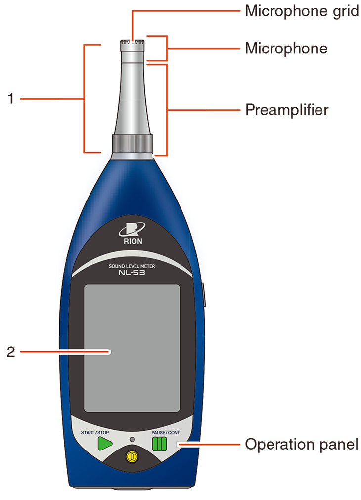
Front
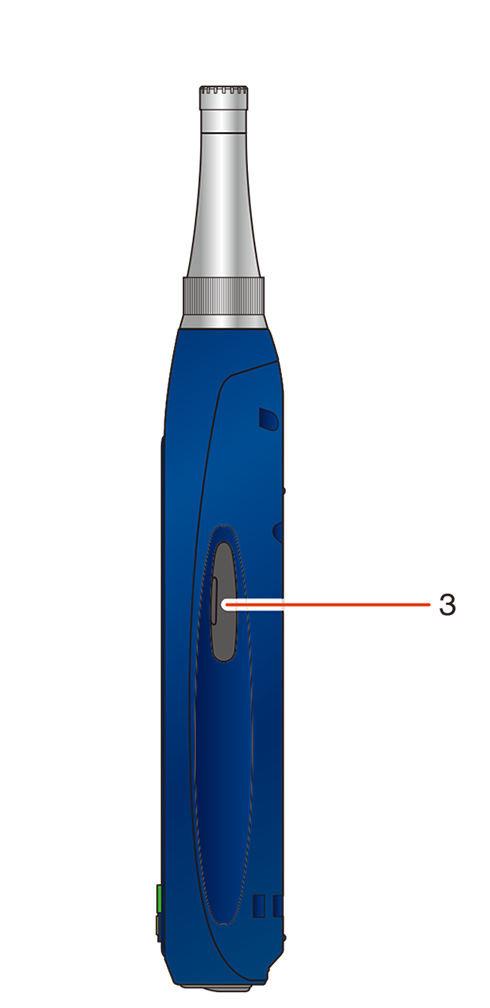
Right side
| No. | Name | Description |
|---|---|---|
| 1 | Microphone and preamplifier |
The microphone and preamplifier can be separated from the main unit. They can be installed at a distance from the main unit using an extension cable (optional). |
| 2 | Touch panel | LCD display with backlight. The sound level is displayed numerically and as a bar graph. Also displayed are the operating status of the device, set measurement conditions, warnings, and other information. The display can be operated by touch. |
| 3 | Card slot (SD) | A slot for inserting an SD card. |
Note
- Do not use a microphone and preamplifier other than those indicated on the serial number label on the back of the device.
- Make sure the microphone and microphone grid are installed securely before using or storing the device.
If there is any looseness, retighten the microphone and microphone grid before using or storing the device.
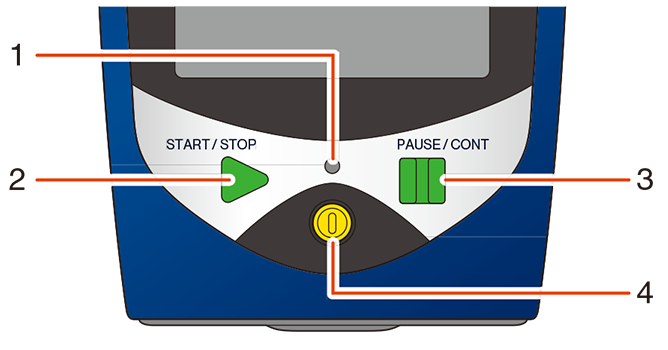
Operation panel
| No. | Name | Description |
|---|---|---|
| 1 | Indicator LED | Lights or flashes red or blue depending on the operation and status of the device. |
| 2 | START/STOP key | Used when starting or ending measurement. Press the START/STOP key on the current measurement screen to start the measurement. Press again to end the measurement. Returns to the measurement screen if pressed while operating the menu. |
| 3 | PAUSE/CONT key | Used to pause the screen display. Also, when pressed during measurement in Manual mode, measurement can be paused. Press again to resume. During PAUSE while measuring in Manual mode, the indicator LED flashes blue. * When back erase is set, you can omit from the calculation the measured values from the time of pressing up to several seconds before (1, 3, or 5 seconds can be selected). Returns to the previous screen if pressed while operating the menu. |
| 4 | POWER key | Press and hold for several seconds to turn the power on or off. To forcibly turn the power off when the key lock is enabled, press and hold for 10 seconds or longer. |
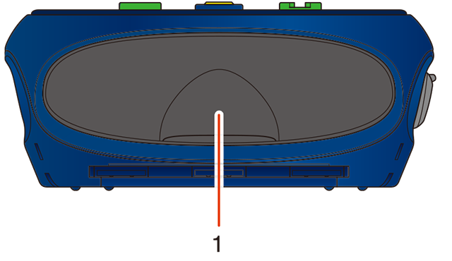
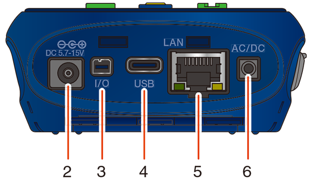
Bottom
| No. | Name | Description |
|---|---|---|
| 1 | Bottom cover | A cover to protect the ports. Ports can be accessed by opening the bottom cover. |
| 2 | External power supply port (DC IN) | This is the port for connecting AC Adapter NE-21P (optional) (input voltage of 100 V to 240 V, 50/60 Hz). You can also use DC Polarity Converter CC-43J (optional) by connecting it to the NC-98 series dedicated AC adapter for sound level meters NL-42A/52A/62A and NL-42/52/62. The Battery Pack BP-21A (optional) can also be used by connecting CC-43J (“Connecting an external power supply”). |
| 3 | I/O port | An RS-232C port for connecting a computer or printer. |
| 4 | USB port (Type-C) | A port for connecting a computer. It is also possible to connect a commercially available USB charger such as a mobile battery to supply power via USB. |
| 5 | LAN port | A port for connecting a computer or router. |
| 6 | AC/DC port | This port outputs AC signals corresponding to the sound pressure waveform after frequency weighting, and DC signals corresponding to the sound level after frequency weighting and time weighting. |
Important
- To maintain the dustproof and waterproof performance, close the bottom cover securely when using the device.
- Do not use AC adapters or battery packs other than the specified ones. Doing so may result in a malfunction.
- The AC/DC port can output simultaneously using the AC/DC Output Splitter Cable CC-43S (optional).
- When using the AC adapter NC-98 series to operate the device, be sure to use the DC Polarity Converter CC-43J (optional).
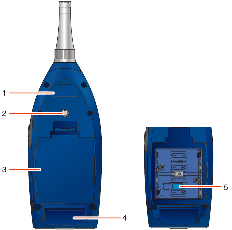
Back
| No. | Name | Description |
|---|---|---|
| 1 | Serial number label | The serial numbers of the microphone, preamplifier, and sound level meter are listed here. |
| 2 | Tripod mounting screw | This screw can be used to mount the device to a camera tripod. |
| 3 | Battery compartment | install four AA batteries to use the device. There is a power-on mode switch in the battery compartment (“Turning on/off the power”). |
| 4 | Nameplate | It shows necessary information such as the model, date of manufacture, and applicable standards of the device. |
| 5 | Sticker | The sticker guarantees the dustproof and waterproof performance of the unit. |
Important
- Do not remove the sticker on the rear of the unit. If the sticker is removed, the “water and dust resistant performance” of the unit is no longer guaranteed.