6.6 I/O
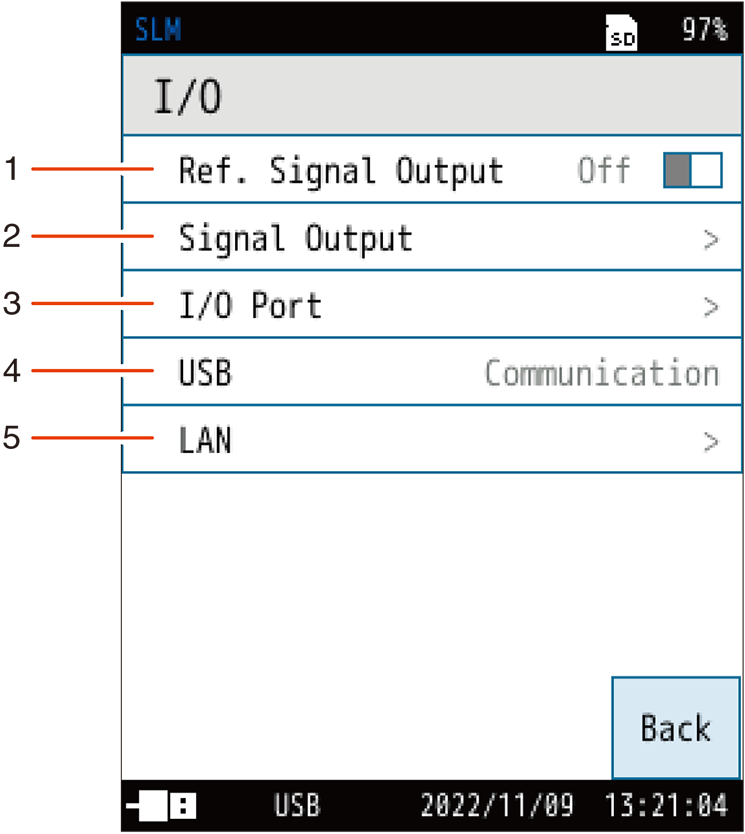
This screen is used to set the types of signals to be input and output externally.
| No. | Name | Description |
|---|---|---|
| 1 | Ref. Signal Output | Outputs the reference signal. |
| 2 | Signal Output | Sets the AC and DC output. |
| 3 | I/O Port | Sets the I/O port on the bottom of the device. |
| 4 | USB | Sets the USB port on the bottom of the device. |
| 5 | LAN |
Sets the LAN port on the bottom of the device. |
6.6.1 Ref. Signal Output
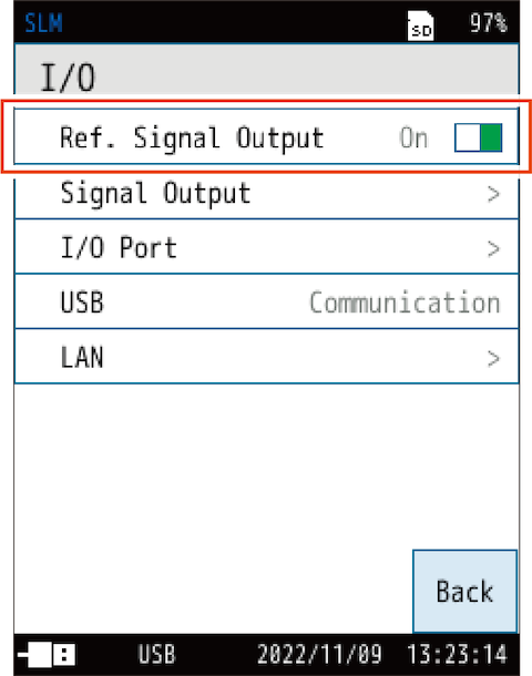
When set to [On], a reference signal is output from inside the main unit and used for calibrating external devices and wave recording data.
Ref.is displayed on the screen at this time.
Frequency : 1 kHz
Output Level : Bar graph range upper limit - 6 dB
Note
When the [Ref. Signal Output] is set to [On], the following settings are automatically changed (the settings will not return to as they were even if [Ref. Signal Output] is set to [Off]).
- Sub channel : Off
- Windscreen Correction : Off
- Diffuse S.F. Corr. : Off
- Time Weighting : F
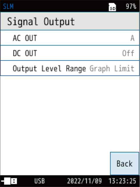
6.6.2 Signal Output
Sets the AC and DC output.
| Item | Description |
|---|---|
| AC OUT | Sets the AC signal output from the AC/DC port on the bottom of the device. |
| DC OUT | Sets the DC signal output from the AC/DC port on the bottom of the device. |
| Output Level Range | Sets the upper limit of the output level range. |
Important
- Make sure that the dedicated accessories, such as the optional BNC-pin output cable CC-24/CC-24S or the AC/DC Output Splitter Cable CC-43S, are connected. Connecting the wrong cable or adapter may damage the device.
Note
- Simultaneous output of AC output and DC output is possible. To output either AC output or DC output, use CC-24/CC-24S. To output them simultaneously, use CC-43S.
- When the AC/DC Output Splitter Cable CC-43S is connected and either the AC or DC is turned on, the output will always be from Channel 1. If both are turned on, the AC output will be from Channel 1 and the DC output will be from Channel 2.
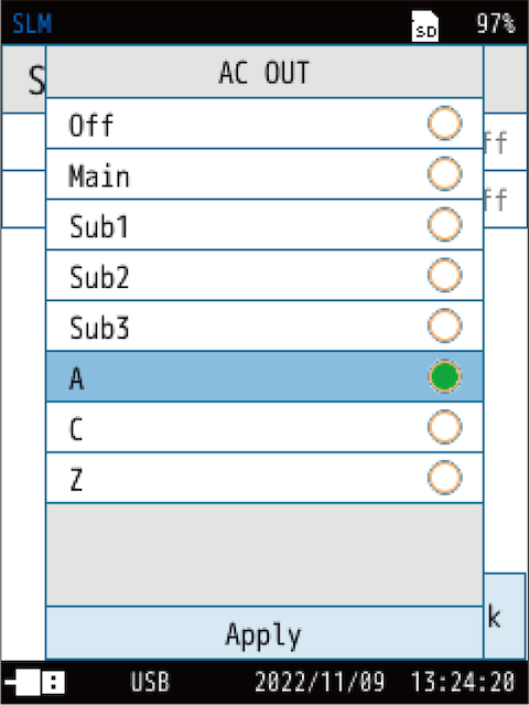
AC OUT
| Item | Description |
|---|---|
| Off | No AC signal is output. |
| Main | Outputs an AC signal corresponding to the sound pressure waveform after frequency weighting. Applies the frequency weighting set in the selected channel. |
| Sub1 | |
| Sub2 | |
| Sub3 | |
| A | Outputs an AC signal corresponding to the sound pressure waveform after frequency weighting. Applies the selected frequency weighting. |
| C | |
| Z |
DC OUT
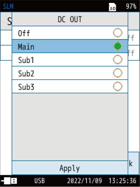
| Item | Description |
|---|---|
| Off | No DC signal is output. |
| Main | Outputs a DC signal corresponding to the sound level (Lp) after frequency weighting and time weighting. Applies the frequency weighting and time weighting set for the selected channel. |
| Sub1 | |
| Sub2 | |
| Sub3 |
Output Level Range
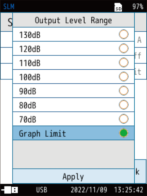
| Item | Description |
|---|---|
| 130dB | Sets the upper range of AC output and DC output. When set to 70 dB to 130 dB, the displayed text color changes (“Information display bar”). |
| 120dB | |
| 110dB | |
| 100dB | |
| 90dB | |
| 80dB | |
| 70dB | |
| Graph Limit | Sets it to the same upper limit as the bar graph. |
6.6.3 I/O Port
Sets the I/O port on the bottom of the device.
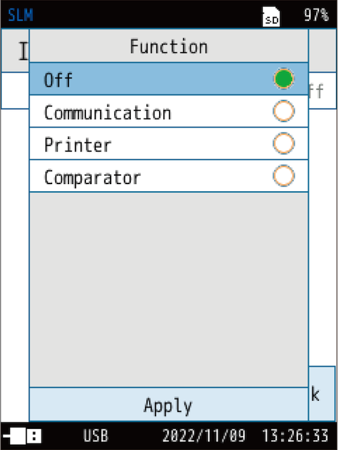
| Item | Description |
|---|---|
| Off | Turns off the I/O setting of the I/O port. |
| Communication | Measurement values can be acquired and settings can be changed by using communication commands. |
| Printer | The contents on the screen can be printed using the dedicated printer DPU-414 or BL2-58. * DPU-414 and BL2-58 are no longer manufactured and sold. |
| Comparator |
Sets the comparator signal (open collector signal for external device control). |
When [Communication] is selected
![When [Communication] is selected](../images/06/06_img_8.png)
Measurement values can be acquired and the baud rate can be changed by using communication commands.
| Item | Description |
|---|---|
| UART Baud Rate | The baud rate can be selected from 9600 bps, 19200 bps, 38400 bps, 57600 bps, and 115200 bps. |
When [Printer] is selected
![When [Printer] is selected](../images/06/06_img_9.png)
The contents on the screen can be printed using the dedicated printer DPU-414 or BL2-58.
| Item | Description |
|---|---|
| DPU-414 | Select the printer to use from DPU-414 and BL2-58. |
| BL2-58 |
When [Comparator] is selected
![When [Comparator] is selected](../images/06/06_img_10.png)
The comparator output turns on when the specified channel exceeds the set level.
| Item | Description |
|---|---|
| Channel | Select the channel to be subject to the comparator’s judgment. |
| Comparator Level | Sets the level for which the comparator output is turned on. |
• Comparator output

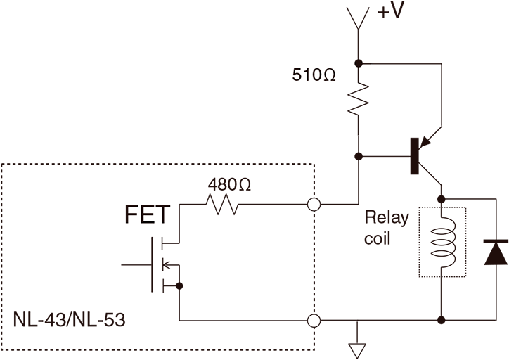
• Example of comparator output circuit
An example of a circuit for controlling a relay by the comparator output of NL-43/NL-53 is shown below.

The voltage applied to the relay when the comparator is turned on is per the following formula.

If the coil resistance of the relay used is large enough compared to the internal resistance of 480 Ω in the NL-43/NL-53, most of the power supply voltage will be applied to the relay.
If the coil resistance is not large enough, the voltage applied to the relay will be divided between the internal resistors within the NL-43/NL-53. As a result, if the operating voltage of the relay is not achieved, the following electrical circuit should be used to eliminate the effects of the internal resistance within the NL-43/NL-53.
6.6.4 USB
Sets the USB port on the bottom of the device.
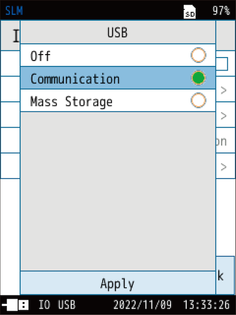
| Item | Description |
|---|---|
| Off | Turns off the I/O setting of the USB port. |
| Communication | Measurement values can be acquired and settings can be changed by using communication commands. |
| Mass Storage | Enables the transferring of data by making the computer recognize the SD card as a removable disk. |
Note
- The USB port can be used for both [Communication] and [Mass Storage].
For details, refer to the “Communication Guide”.
6.6.5 LAN
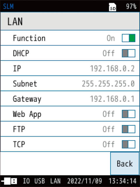
The IP address on the screen is an example.
Sets the LAN port on the bottom of the device.
The LAN port communicates with the IP address specified by the user or automatically obtained from the router, and it can be controlled by commands, acquire data, and display a web browser. For details, refer to the “Communication Guide”.
| Item | Description |
|---|---|
| Function | Sets On/Off for the LAN function. |
| DHCP | Automatically sets the IP address of the sound level meter. |
| IP | Sets the IP address of the Sound Level Meter and displays the current settings. |
| Subnet | Sets the subnet mask and acquires the current setting. |
| Gateway | Sets the default gateway and acquires the current setting. |
| Web App | Turns On/Off the web app. To use the web app, set it to [On]. * It is recommended to use the web browser Google Chrome on a computer. The sound will not play on other web browsers. |
| FTP | Sets On/Off for file transfer. |
| TCP | Turns on/off the communication control. |